Designing a Vtol Mechanism from scratch
Introduction
A project that I have been working on needed a Vertical takeoff or landing (VTOL) tilt mechanism for the the front 2 motors, so here is how I went about designing and testing it. It can be challenging to hand launch a twin motor plane as you have to worry about both prop disc areas, while managing controls, and adding a vtol system can allow for operations where a wheel based takeoff is not a possibility
The specifications of the propulsion system are a Emax 2213-935KV brushless motor, that spins a 8045 prop, with a spider 20apm opto esc, using a 4 lithium polymer cell battery. This power systems is typically used in quad copters such as a dji flamewheel 450. The servos for tilting the motor varied depending on the design of the tilting mechanism.
 |
| Figure 1. A dji flamewheel 450 quadcopter, with a propulsion system similar to the VTOL's system |
Goals
The goals of this project was to be able to develop a vtol tilt system for a uav that is in the process of being built and designed. The criteria for the parts were that they had to give a full 90 degree range of motion for the motor, not show any signs of stress under a full throttle load, be as light as possible and have the fewest moving parts.
Methods
The parts were designed in Autodesk Fusion-360, and were printed out of pla on a TronXY- XY 2 pro. The use of a 3d printer allowed for rapid prototyping and which reduced the time between testing designs.
Design 1
 |
| Figure 2. The the first design for the vtol tilt mechanism |
This design used a 9 gram metal geared servo, and push rods to rotate the motor. This design was based off of the Eflite convergence vtol. (Figure ) It was tested under limited conditions, using a 3 cell lipo to run the motor, so max thrust was not achieved, as locations that could fail were discovered while installing the electronics.
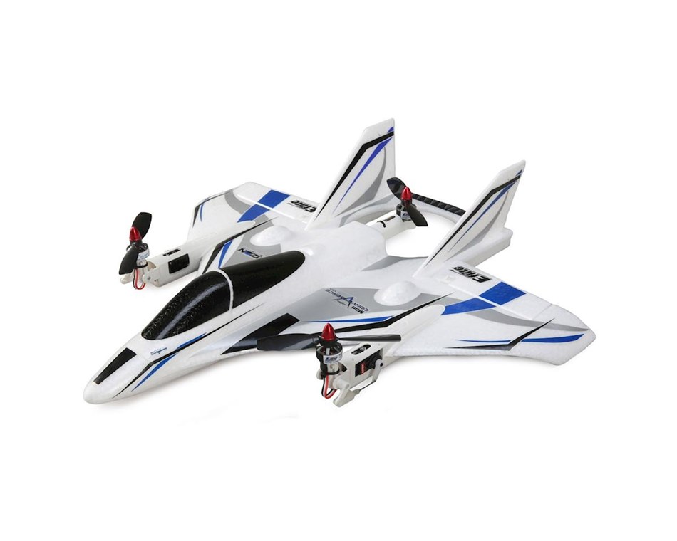 |
| Figure 3. A Eflite convergence vtol, an inspiration for the tilt mechanism for design 1 |
From the video a few key issues can be seen, the biggest being that the motor never reaches a full vertical position, which would lead the uav to move forward while hovering. Another issue was that there was some "slop" in the system, which caused the motor to vibrate. This motor vibration would not only reduce the quality of the sensor, but also the vibration could stress and crack the mechanism. Another issue appeared while disassembling the tilt mechanism, the push rods were bent (IMAGE), this would lead to a reduction in control for the servo for tilting the motor.
Even with all of those failures there were a few successes in this test, the main one being the 3d printed parts could withstand the forces of the motor at 20% infill, which means light parts are possible. Another success was that a cheap 9 gram servo was able to rotate the motor, as this also allows for a reduction in weight.
After the data collection in that first test it was back to CAD to design a new mechanism.
Design 2
 |
| Figure 4. a picture of the v2 vtol tilt |
 |
| Figure 5. a side view of the vtol |
This design is a direct driven tilt mechanism, this style of direct driven motor tilt is usually see in tricopters. (Photo of tricopter tail) A benefit of this design is that it removes the weak push rods, and reduces the size of the part. A draw back is that it uses a heaver more expensive servo.
(Video)
From the video we can see that this mechanism can rotate a full 90 degrees. The design also has a lot less slop than the first design, which should reduce the potential for vibration and resistance frequency based structural failure. Another thing to note from this design is that the motor mount is sleeker, and will create less drag as the servo is now in line with the motor and not above it.
Discussion
This was a good visual inspection and test of the dynamics of the motor tilt system, but further analysis would be needed for a complete test of the designs, and could provide more optimization to the system. Some of the things that were not tested for were torque that the servo had to output to tilt the motor. Not testing the torque for the motor could lead to having too high of a torque need to rotor the tilt mechanism, and burning out the servo. Also the torque could be significantly less than the servo outputs and the servo could be heavier than required.
Conclusion
While this test did not cover all of the possibilities, or figure out the mean time till failure, it is enough for this project to move onto a flight operations stage to see if it is possible to sustain a hover with an aircraft weighing approximately 3 lbs.
Sources
Figure # Eflite convergence vtol photo from https://store.flitetest.com/eflite-mini-convergence-vtol-bnf-basic-electric-airplane-410mm-efl9350/p792275


Comments
Post a Comment